|
Setting-up the LocoNet® of a modular layout on a FREMO meeting, a tester is quiet useful. But it is usually sufficient to check the voltage levels. Such a simple tester is described below. |
|
As the boosters are driven by the differential voltage between the two RailSync lines the voltage of these two lines should be measured against each other. A difference of 6 V should be sufficient. The LocoNet® operates with a threshold of 4 V with a hysteresis of 1 V. For safe operation levels of 3 and 5 V should be crossed. Therefore LEDs for the following states have been implemented: 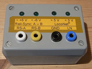
At error free operation the first three LEDs are on, the fourth blinks depending on the activity on the LocoNet®. The following error conditions may be distinguished:
This covers the most frequent errors. |
|
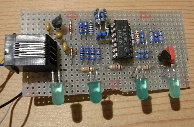
The circuitry is available as PDF file. The active parts are only a voltage regulator, a quad comparator and a FET. The voltage regulator may be a low voltage drop type. There are no critical parameters for the enhancement P-channel FET. Therefore any other type may be used, but the pinout must be checked. |
|
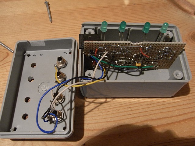
The tester uses the same box as the LN-boxes, but just with a single LocoNet® socket. The manufacturing data for the single sided PCB (drill drawing, place plan and layout) are available as PDF file. The hole positions marked 'A' and 'C' should be drilled with 0.7 to 0.8 mm (28 to 32 mil), those marked 'D' with 3,1 mm (1/8 inch). The holes marked 'B' are feed-throughs for the wires to the 4 mm banana jacks and may be drilled with a maximum diameter of 1.4 mm (55 mil). The LEDs are soldered to the board with nearly unshortened leads and bent to the top to look through the 5 mm holes in the box. The 4 mm banana jacks are connected with the four signals at the RJ12 socket to allow further measurements. As the 4 mm banana jack are located on the other side of the board as the LEDs, the wires have to be feed from the solder side. Initially a BSS92 was used instead of the BSS110, which is easier to get but has a different pinout. For the BSS92 version the manufacturing data is also available. Please note that in the drill drawing the letters 'B' and 'D' have swapped their meaning relative to the BSS110 version |
|
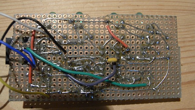
I build my own tester without an etched board but on a simple hole matrix board. The three images show the construction. The arrangement of the parts follows roughly the placement plan.
|
| Number | Type | Reference | Description | Conrad part # | price / piece | Reichelt part # | price p. piece |
|---|---|---|---|---|---|---|---|
| 1 | 1K | R37 | Resistor, metal film 1 % | 41 82 50-66 | -,15* | metall 1K | -,09* |
| 4 | 1K | R15 R25 R39 R41 | Resistor, 5 % | 40 32 53-66 | -,13* | 1/4W 1K | -,065* |
| 3 | 12K | R14 R24 R35 | Resistor, metal film 1 % | 41 83 82-66 | -,15* | metall 12K | -,09* |
| 2 | 20K | R12 R22 | Resistor, metal film 1 % | 42 08 91-66 | -,15* | metall 20K | -,09* |
| 4 | 24K | R10 R11 R20 R21 | Resistor, metal film 1 % | 42 09 05-66 | -,15* | metall 24K | -,09* |
| 3 | 30K | R13 R23 R36 | Resistor, metal film 1 % | 42 09 13-66 | -,15* | metall 30K | -,09* |
| 1 | 82K | R33 | Resistor, metal film 1 % | 41 84 80-66 | -,15* | metall 82K | -,09* |
| 2 | 100K | R31 R32 | Resistor, metal film 1 % | 41 84 98-66 | -,15* | metall 100K | -,09* |
| 1 | 330K | R34 | Resistor, metal film 1 % | 41 85 52-66 | -,15* | metall 330K | -,09* |
| 1 | 1M | R38 | Resistor, metal film 1 % | 41 86 17-66 | -,15* | metall 1M | -,09* |
| 1 | 68nF | C4 | MKS Capacitor | 45 53 85-66 | -,47 | MKS-2 68n | -,19 |
| 2 | 100nF | C2 C3 | Ceramic Capacitor | 45 33 82-66 | -,95 | X7R-5 100n | -,24 |
| 1 | 1uF | C1 | Electrolytic Capacitor | 48 16 70-66 | -,57 | Tantal 1,0/35 | -,19 |
| 2 | BAT46 | D1 D2 | Schottky Diode | 15 30 87-66 | -,90 | BAT 46 | -,21 |
| 1 | BSS110 | Q1 | P Channel MOSFET | ||||
| 4 | LED green | D10 D20 D30 D40 | 5mm LED green TLLG 5400 | 18 69 29-66 | -,65 | TLLG 5400 grün | -,17 |
| 1 | LM339 | U1 | Quad Comparator | 17 60 36-66 | 1,00 | LM 339 DIL | -,36 |
| 1 | LM78L05 LP2950CZ |
U2 | 5 V voltage Regulator alternatively Low Voltage Drop Type |
18 30 24-66 17 56 76-66 |
-,75 4,95 |
UA 78L05 | -,40 |
| 1 | RJ12 | J1 | RJ12 6 pole modular socket | 28 1 03-66 | 2,95 | MEBP 6-6S | 1,30 |
| 1 | Box | 52 08 61-66 | 6,25 | ||||
| 1 | 4mm banana jack white (RS-A) | 73 40 63-66 | -,75 | BB4 weiß | -,56 | ||
| 1 | 4mm banana jack yellow (RS-B) | 73 40 39-66 | -,75 | BB4 gelb | -,56 | ||
| 1 | 4mm banana jack black (GND) | 73 40 20-66 | -,75 | BB4 schwarz | -,56 | ||
| 1 | 4mm banana jack blue (LN) | 73 40 47-66 | -,75 | BB4 blau | -,56 | ||
| 4 | Soldering tab | 53 18 98-66 | -,11* | not needed | |||
| 08.01.2000 |