|
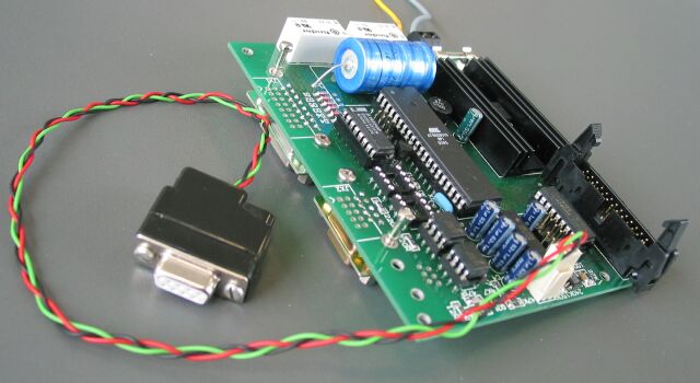
Translation note: Not all terms could be translated. Those terms are marked with a (D) for "Deutsch". This page describes the first version of the hardware for the electronic absolute block system. The second version is already in use. The design is based on the station interface in relay technique and the electronic block interface. Additionally there are interfaces for the diagnosis and an optional electronic station interface. The design is spilt into the logic part, containing the microcontroller and all interfaces, and a user interface, which depends on the type of prototype block. This results in an additional connector to the user interface. First photo of the first version ....
On this page only the logic part is described. Following are links to the interface descriptions and user interfaces as far as available.
|
|
The ports PB5 to PB7 are used for the programming of the microcontroller as well. During programming these ports see fast clocking signals. Therefore only user interface loads, able to tolerate the fast switching without producing excessive noise, should be connected to these ports. In case a single board is used for a double track route (only possible with uni-directional tracks), the ports PB1 to PB3 are used for the station interface and therefore may not be used for the user interface. In case the ports PB1 to PB2 are used in a single track application the two optocouplers U45 and U44 may not be placed on the board! JP1 selects incoming data:
This data is only for an optional electronic station interface. In normal use with the station interface in relay technique it is not needed. JP2 selects the voltage for the relay of the station interface:
The second option allows to reduce the power dissipation of the 5 V regulator. Additionally relays for higher voltages need less current. |
|
The parts list for the first board version is available as Excel table*). In the lower part different possibilities for the power supply are compared. This is ... still to be worked at. Some parts are only needed for some options and may be left out. The options and the corresponding parts are:
*) If there is only one line with tall cells visible when opened, |