|
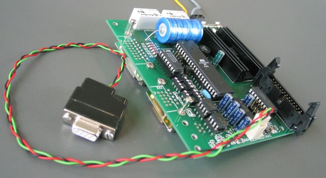
Translation note: Not all terms could be translated. Those terms are marked with a (D) for "Deutsch". This page describes the second version of the hardware for the electronic absolute block system. The first version is still available on a separate page. The changes are minor, i.e. for the user the versions are (almost) identical. Only the connector for an internal LOTUSnet has been added. The image shows the first version of the logic part. A third order campain is planned, but there will be no changes to the board. The design is based on the station interface in relay technique and the electronic block interface. Additionally there are interfaces for the diagnosis and an optional electronic station interface. The design is spilt into the logic part, containing the microcontroller and all interfaces, and a user interface, which depends on the type of prototype block. This results in an additional connector to the user interface.
On this page only the logic part is described. Following are links to the interface descriptions and user interfaces as far as available.
|
|
The ports PB5 to PB7 are used for the programming of the microcontroller as well. During programming these ports see fast clocking signals. Therefore only user interface loads, able to tolerate the fast switching without producing excessive noise, should be connected to these ports. In case a single board is used for a double track route (only possible with uni-directional tracks), the ports PB1 to PB3 are used for the station interface and therefore may not be used for the user interface. In case the ports PB1 to PB2 are used in a single track application the two optocouplers U45 and U44 may not be placed on the board! The capacitors C17 and C18 (22 nF) are only placed on the board, if a quartz is used instead of the resonator X1. Otherwise these pads stay empty. JP1 selects incoming data:
This data is only for an optional electronic station interface. In normal use with the station interface in relay technique it is not needed. In the configuration with pins 2 and 3 connected the LOTUSnet interface is used as connection between internal and external LOTUSnet. Only if the connector for the external interface is not used, no connection should be made, as without external pull-up a logic zero is received, blocking the internal LOTUSnet. JP2 selects the voltage for the relay of the station interface:
The second option allows to reduce the power dissipation of the 5 V regulator. Additionally relays for higher voltages need less current. |
|
The parts list for the second board version is available as Excel table. Some parts are only needed for some options and may be left out. The options and the corresponding parts are:
As the cost for the parts are below 2 Euro per option, in the interest of a general usability it makes sense to populate at least all SMD parts. But U44 and U45 should be only placed if needed. As the JTAG interface is only used by a few programmers - a software update is always possible via J7 "ISP" - the connector J8 is not part of the commonly bought parts. |
|
With all boards the following informantion was distributed to help assembling the board.
|
|
This is a list of PDF files of the main layers and plots. |