|
|
[Track Switch] [LocoNet Gateway] |
|
|
[Track Switch] [LocoNet Gateway] |
|
For both the track power switch and the LocoNet Gateway the case "SP 2063 GR" from Reichelt with the dimensions 165 x 88 x 28 mm is used. The construction of both devices is quite similar and therefore there is a common description. Following the links to the drawings and drill templates.
The bottom part of the case should be orientated with the two posts for board mounting, which are not in one of the corners, are more to the left. Then they will not conflict with anything in the LocoNet Gateway. With the track switch even in this orientation one of the posts has to be removed before the holes for the banana jacks are drilled. The holes for hanging up the case should be drilled now as well. They are the same for both cases and are connected using a file according to the drawing.
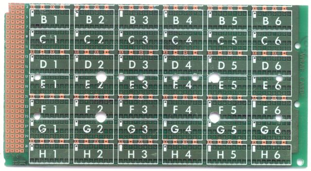
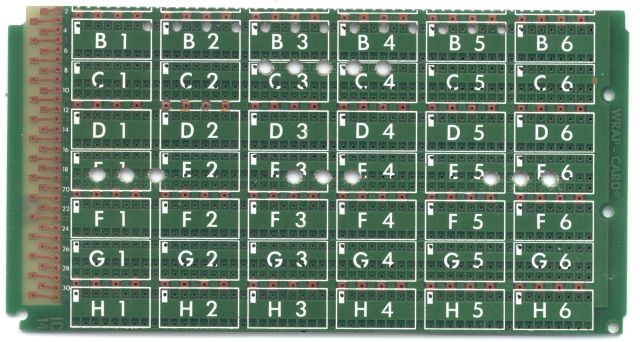
The holes for the LEDs are drilled using the drill template, which have been made from old Wire Wrap cards. Due to one corner of the lid being bigger these templates fit only in one orientation. In the picture the corresponding cut-out is at the top left. Attention has to be paid when drilling the holes for the track switch, as the holes for the LEDs D1 and D2 as well as the lamps L1 and L2 in the fields D3/E3 and D4/E4 are not drilled. These parts will not be used. In the template for the LocoNet Gateway there is a row of 2 mm holes. These are not drilled into the front face but on the top edge, to get rid of the heat from the RSCLD resistors. To drill these holes the template has to be clamped to the small side and adjusted to the edge using the printed lines. When drilling the holes for the Cinch connectors or the low voltage power plug the case must be put together the right way round. The small end of the hols for hanging up and the bigger corner in the top part to the top. For drilling the case should be clamped between two thick metal plates. Otherwise the case can not be securely clamped vertically in a vice. The centre of the holes is in the top part 1.8 mm from the outer edge. First a small drill for plastic is used and then the hole is enlarged by use of a spot facer of 12 mm for the Cinch connectors and 11 mm for the low power voltage plug. Otherwise it is very difficult to get clean holes at the right position. The socket for the low voltage power plug of the LocoNet Gateway has not a tight fit on the board. Therefore its position is not very precise. Therefore I first made the cut-outs for the LocoNet connectors in the bottom part, placed the board in the bottom part and marked the true position. The board is populated completely except for the LEDs. Then the board is placed with the LocoNet connectors on the edges of the bottom part. After aligning the board with all connectors being at the edge or having all the same offset, a cutter is used to mark the position of the connectors. The depth of the cut-out of 4.7 mm is marked with a slide caliper, and then sawed at the sides; the marking at the lower edge is deepened with a cutter and the main part broken out to the inside. The rest is a job for the key file. The cut-out for the D-SUB connector of the logging interface of the LocoNet Gateway should be 4.0 mm in the bottom part. After the cut-outs for the LocoNet connectors have been finished in the bottom part, the case is put together without the board and the position of the connectors is copied to the top part. There 10.6 mm deep cut-outs, reaching close to the top face of the case, are made the same way as in the bottom part. The cut-out for the D-SUB connector should be 6.5 mm in the top part. After the cut-outs in the top part are finished as well, the LEDs are placed in board, keeping attention to the colours and polarity. The top part is placed on top of the board and this assembly is turned over, letting the LEDs falling into their holes. Placing this on a flat surface insures the LEDs to be flush with the case surface. Now the LEDs may be soldered, insuring that the light LEDs are not unintentionally lifted by the soldering iron. In case the LocoNet connectors of the track power switch have not been assembled, Cinch connectors may be used instead, but will result in poorer alignment then with the LocoNet connectors installed. Following a functional test all should be assembled and with the track power switch the jacks for track power and power supply should be connected to the screw terminals using short wires. |
|
|
[Track Switch] [LocoNet Gateway] |